 |
Phoenix quick facts
- Landed on Mars in the frigid northern polar region
- Is to investigate whether ice sometimes melts enough to support life
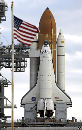
- Launch was from Cape Canaveral on Delta II rocket
- Robotic arm digs through the soil to the water-ice underneath
- Arm to deliver soil, ice samples to mission's experiments
Source: BBC |
Overview
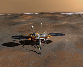
A Mars lander, launched on August 4, 2007, which successfully landed on the Martian northern plains on May 25, 2008. Phoenix is the first mission in NASA's Scout Program and the sixth successful Mars lander. It is specifically designed to measure volatiles(especially water) and complex organic molecules in the arctic plains of Mars, where the Mars Odyssey orbiter has discovered evidence of ice-rich soil very near the surface.
Similar to its mythical namesake, Phoenix has risen from the ashes of an earlier version of itself – in fact, from the instruments and other hardware of two previous unsuccessful attempts to explore Mars. Phoenix uses a lander that was intended for use by 2001's Mars Surveyor lander prior to its cancellation and carries a complex suite of instruments that are improved variations of those that flew on the lost Mars Polar Lander.
In the continuing pursuit of water on Mars, the Martian poles are a good place to investigate, as water ice is found there. Phoenix landed on the icy northern pole of Mars near 68° north latitude, 127° west longitude. During the course of the 150-Martian-day mission, Phoenix will deploy its robotic arm (see below) and dig trenches up to half a meter (1.6 ft) deep into the layers of water ice. These layers, thought to be affected by seasonal climate changes, could contain organic compounds that are necessary for life.
Having arrived on the surface of Mars, Phoenix began to take detailed photos of its new surroundings. Imaging technology inherited from both the Pathfinder and Mars Exploration Rover missions has been implemented in Phoenix's stereo camera, located on its 2-meter (6.6-ft) mast. The camera's two stereoscopic eyes can provide a high-resolution perspective of the landing site's geology, and also provide range maps that will enable the mission's science team to choose ideal digging locations. Multi-spectral capability will enable the identification of local minerals.
To analyze soil samples collected by the robotic arm, Phoenix carries a miniature oven and a portable laboratory. Selected samples will be heated to release volatiles that can be examined for their chemical composition and other characteristics.
To update our understanding of Martian atmospheric processes, Phoenix will scan the Martian atmosphere up to 20 km (12.4 miles) in altitude, obtaining data about the formation, duration and movement of clouds, fog, and dust plumes. It will also carry temperature and pressure sensors.
To see photos taken by the Phoenix Lander, go here.
Science instruments
Robotic Arm (RA)
The Robotic Arm (RA) is intended to dig trenches, scoop up soil and water ice samples, and deliver these samples to the TEGA and MECA instruments (see below) for detailed chemical and geological analysis. Designed similar to a back hoe, the RA can operate with four degrees of freedom: (1) up and down, (2) side to side, (3) back and forth, and (4) rotate around.
The RA is 2.35 meters (just under 8 ft) long with an elbow joint in the middle, allowing the arm to trench about 0.5 m (1.6ft) below the Martian surface, deep enough to where scientists believe the water-ice soil interface lies. At the end of the RA is a moveable scoop, which includes ripper tines (sharp prongs) and serrated blades. Once icy soil is encountered, the ripper tines will be used to first tear the exposed materials, followed by applying the serrated blades to scrape the fractured soil. The scoop will then be run through the furrows to capture the fragmented samples, ensuring enough sample mass for scientific study on the lander platform.
Robotic Arm Camera (RAC)
Built for the Mars Surveyor 2001 Lander, the RAC is attached to the Robotic Arm (RA) just above the scoop. The instrument provides close-up, full-color images of (1) the Martian surface in the vicinity of the lander, (2) prospective soil and water ice samples in the trench dug by the RA, (3) verification of collected samples in the scoop prior to analysis by the MECA and TEGA instruments, and (4) the floor and side-walls of the trench to examine fine-scale texturing and layering.
By examining the color and grain size of scoop samples, scientists will better understand the nature of the soil and water-ice in the trench being dug by the RA. Additionally, floor and side-walls images of the trench may help determine the presence of any fine-scale layering that may result from changes in Martian climate.
The RAC is a box-shaped imager with a double Gauss lens system, commonly found in many 35 mm cameras, and a charged-coupled device similar to those found on many consumer digital cameras. Two lighting assemblies provide illumination of the target area. The upper assembly contains 36 blue, 18 green, and 18 red lamps and the lower assembly contains 16 blue, 8 green, and 8 red lamps. The RAC has two motors: one sets the lens focus from 11 mm to infinity and the other opens and closes a transparent dust cover. The instruments magnification is 1:1 at closest focus, providing image resolutions of 23 microns per pixel.
Microscopy, Electrochemistry, and Conductivity Analyzer (MECA)
MECA is designed to characterize the soil of Mars much like a gardener would test the soil in his or her yard. By dissolving small amounts of soil in water, the wet chemistry lab (WCL) determines the pH, the abundance of minerals such as magnesium and sodium cations or chloride, bromide and sulfate anions, as well as the conductivity and redox potential. Looking through a microscope, MECA examines the soil grains to help determine their origin and mineralogy. Needles stuck into the soil determine the water and ice content, and the ability of both heat and water vapor to penetrate the soil.
MECA contains four single wet chemistry labs, each of which can accept one sample of martian soil. Phoenix's RA will initiate each experiment by delivering a small soil sample to a beaker, which is ready and waiting with a pre-warmed and calibrated soaking solution. Alternating soaking, stirring, and measuring, the experiment continues until the end of the day. After freezing overnight and thawing the next morning, the experiment continues with the addition of four crucibles containing solid reagents. The first contains an acid to tease out carbonates and other constituents that are better dissolved in an acidic solution. The other three crucibles contain a reagent to test for sulfate.
The optical and atomic-force microscopes complement MECA's wet chemistry experiments. With images from these microscopes, scientists will examine the fine detail structure of soil and water ice samples. Detection of hydrous and clay minerals by these microscopes may indicate past liquid water in the martian arctic. The optical microscope will have a resolution of 4 microns per pixel, allowing detection of particles ranging from about 10 micrometers up to the size of the field of view (about 1 mm by 2 mm). Red, green, blue, and ultraviolet LEDs will illuminate samples in differing color combinations to enhance the soil and water-ice structure and texture at these scales. The atomic force microscope will provide sample images down to 10 nanometers – the smallest scale ever examined on Mars. Using its sensors, the AFM creates a very small-scale topographic map showing the detailed structure of soil and ice grains.
Prior to observation by each of the microscopes, samples are delivered by the RA to a wheel containing sixty-nine different substrates. The substrates are designed to distinguish between different adhesion mechanisms and include magnets, sticky polymers, and "buckets" for bulk sampling. The wheel is rotated allowing different substrate-sample interactions to be examined by the microscopes.
MECA's final instrument, the thermal and electrical conductivity probe, will be attached at the "knuckle" of the RA. The probe consists of three small spikes that will be inserted into the ends of an excavated trench. In addition to measuring temperature, the probe will measure thermal properties of the soil that affect how heat is transferred, providing scientists with better understanding of surface and atmospheric interactions. Using the same spikes, the electrical conductivity will be measured to indicate any transient wetness that might result from the excavation. Most likely, the thermal measurement will reflect ice content and the electrical, unfrozen water content.
Surface Stereo Imager (SSI)
SSI will serve as Phoenix's eyes for the mission, providing high-resolution, stereo, panoramic images of the Martian arctic. Using an advanced optical system, SSI will survey the arctic landing site for geological context, provide range maps in support of digging operations, and make atmospheric dust and cloud measurements.
Situated on top of an extended mast, SSI will provide images at a height two meters above the ground, roughly the height of a tall person. SSI simulates the human eye with its two optical lens system that will give three-dimensional views of the arctic plains. The instrument will also simulate the resolution of human eyesight using a charged-coupled device that produces high density 1024 × 1024 pixel images. But SSI exceeds the capabilities of the human eye by using optical and infrared filters, allowing multispectral imaging at 12 wavelengths of geological interest and atmospheric interest.
Looking downward, stereo data from SSI will support robotic arm operations by producing digital elevation models of the surrounding terrain. With these data, scientists and engineers will have three-dimensional virtual views of the digging area. Along with data from the TEGA and the MECA, scientists will use the three-dimensional views to better understand the geomorphology and mineralogy of the site. Engineers will also use these three-dimensional views to command the trenching operations of the robotic arm. SSI will also be used to provide multispectral images of samples delivered to the lander deck to support results from the other scientific instruments.
Looking upward, SSI will be used to estimate the optical properties of the Martian atmosphere around the landing site. Using narrow-band imaging of the Sun, the imager will estimate density of atmospheric dust, optical depth of airborne aerosols, and abundance of atmospheric water vapor. SSI will also look at the lander itself to assess the amount of wind-blown dust deposited on spacecraft. Deposition rates provide important information for scientists to understand erosional and atmospheric processes, but are critical for engineers who are concerned about the amount of deposited dust on the solar panels and associated power degradation.
Thermal and Evolved Gas Analyzer (TEGA)
TEGA is a combination high-temperature furnace and mass spectrometer instrument that scientists will use to analyze Martian ice and soil samples. The robotic arm will deliver samples to a hopper designed to feed a small amount of soil and ice into eight tiny ovens about the size of an ink cartridge in a ballpoint pen. Each of these ovens will be used only once to analyze eight unique ice and soil samples.
Once a sample is successfully received and sealed in an oven, the temperature is slowly increased at a constant rate, and the power required for heating is carefully and continuously monitored. This process, called scanning calorimetry, shows the transitions from solid to liquid to gas of the different materials in the sample: important information needed by scientists to understand the chemical character of the soil and ice.
As the temperature of the furnace increases up to 1000°C (1800°F), the ice and other volatile materials in the sample are vaporized into a stream of gases. These are called evolved gases and are transported via an inert carrier to a mass spectrometer, a device used to measure the mass and concentrations of specific molecules and atoms in a sample. The mass spectrometer is sensitive to detection levels down to 10 parts per billion, a level that may detect minute quantities of organic molecules potentially existing in the ice and soil.
With these precise measurement capabilities, scientists will be able to determine ratios of various isotopes of hydrogen, oxygen, carbon, and nitrogen, providing clues to origin of the volatile molecules, and possibly, biological processes that occurred in the past.
Meteorological Station (MET)
Throughout the course of Phoenix surface operations, MET will record the daily weather of the Martian northern plains using temperature and pressure sensors, as well as a light detection and ranging (LIDAR) instrument. With these instruments, MET will play an important role by providing information on the current state of the polar atmosphere and how water is cycled between the solid and gas phases in the Martian arctic.
The MET's lidar is an instrument that operates on the same basic principle as radar, using powerful laser light pulses rather than radio waves. The lidar transmits light vertically into the atmosphere, which is reflected off dust and ice particles. These reflected light pulses and their time of return to the lidar instrument are analyzed, revealing information about the size of atmospheric particles and their location.
From this distribution of dust and ice particles, scientists can make important inferences about how energy flows within the polar atmosphere, important information for understanding martian weather. These particles also reveal the formation, duration, and movement of clouds, fog, and dust plumes, improving scientific understanding of Mars' atmospheric processes.
The very cold temperatures of the martian arctic will be measured with thin wire thermocouples, a technology that has been used successfully on meteorological stations for both the Viking and Pathfinder missions. In a thermocouple, electric current flows in a closed circuit of two dissimilar metals (chromel and constantan in the case of the MET) when one of the two junctions is at a different temperature. Three of these thermocouple sensors will be located on a 1.2 meter vertical mast to provide a profile of how the temperature changes with height near the surface.
Atmospheric pressure on Mars is very low and requires a sensitive sensor for measurement. Pressure sensors similar to those used on the Viking and Pathfinder missions will be part of the MET.
Landing site
The Phoenix Lander came to rest in the the northern polar region of Vastitas Borealis at 68.2°N 234.3°W. Images from the spacecraft revealed a flat landscape with a strange "quilted" appearance. The polygonal shapes, defined by trough-like boundaries, had been seen from orbit and were likely created by the repeated expansion and contraction of subsurface ice.
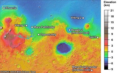 |
Landing sites of Phoenix and early Mars spacecraft
|
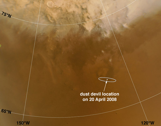 |
Mars Reconnaissance Orbiter image of the region around the Phoenix landing site, taken on April 20, 2008. The landing ellipse, in the lower right quadrant, is about 100 km (60 miles) long. A dot within the landing ellipse marks the location of two active dust devils. When MRO acquired this image, the season in Mars' northern hemisphere was late spring. A few weeks earlier, the Phoenix landing site was still covered with seasonal frost left over from the previous winter.
|